
ARM core board - level conversion circuit (on)
In the circuit design process, electronic engineers often encounter the problem that the I/O level of the processor MCU and the I/O level of the module are not the same. In order to ensure the normal communication between the two, level conversion is required. Below, we will make a detailed analysis of the level shift circuit.
For most MCUs, the pins are basically CMOS structures, so the input voltage range is: high level not lower than 0.7VCC, low level not higher than 0.3VCC.
However, before introducing the level conversion circuit, we need to first understand the following points:
1. Solve the level conversion problem, the most fundamental is to solve the level of compatibility issues, and there are two levels of compatibility principles: 1VOH> VIH2VOL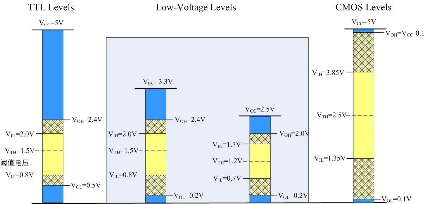
2. For multi-power systems, some devices do not allow the input level to exceed the supply voltage. For devices with similar requirements, the circuit should be properly protected.
3. The level shifting circuit will affect the communication speed, so you should pay attention to the communication speed requirement when using.
4. The driving ability of different conversion methods is different, and should be considered properly in the selection.
5. When there are many ways to convert, improper selection of the conversion method will result in more components or inconvenient wiring.
The following uses the example of Zhiyuan Electronics MiniARM core board to share the commonly used level conversion circuit method.
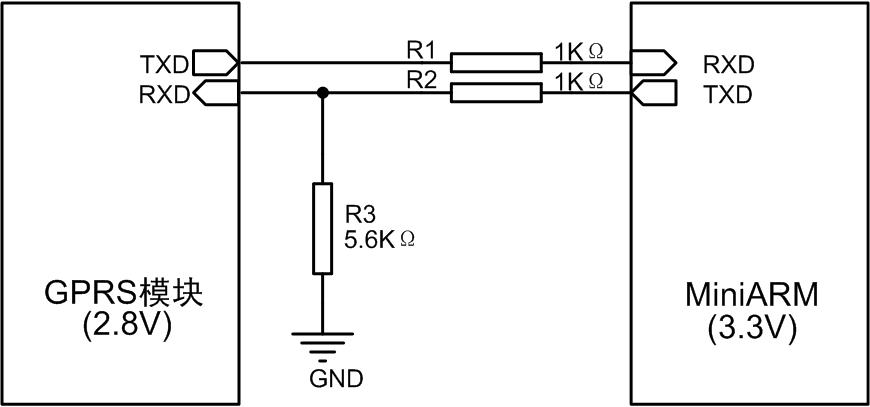
1. Resistive voltage divider The resistive voltage divider method is the simplest method. The circuit works by dividing the logic level high. Take the communication between the MiniARM core board and the GPRS module as an example. The IO level of the MiniARM core board is 3.3V, while the IO level of the GPRS module is 2.8V, and the level matching can be achieved by using FIG. 2 when communicating between the two.
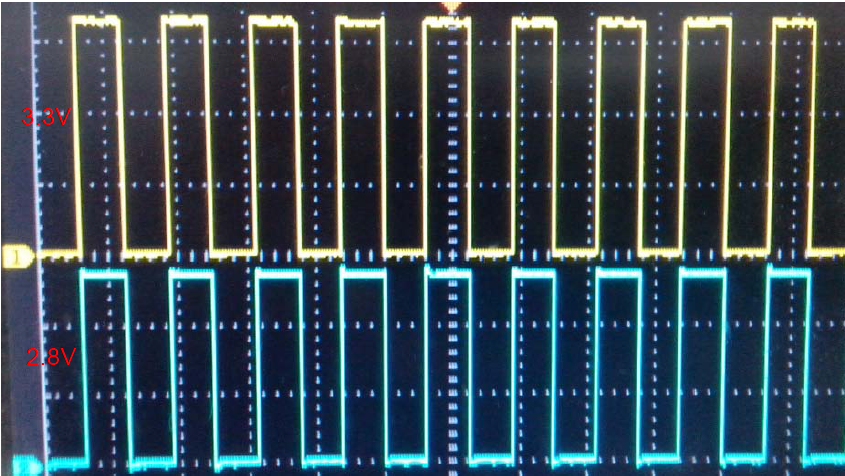
The resistive voltage conversion circuit is tested and the converted waveform is shown in Figure 3.
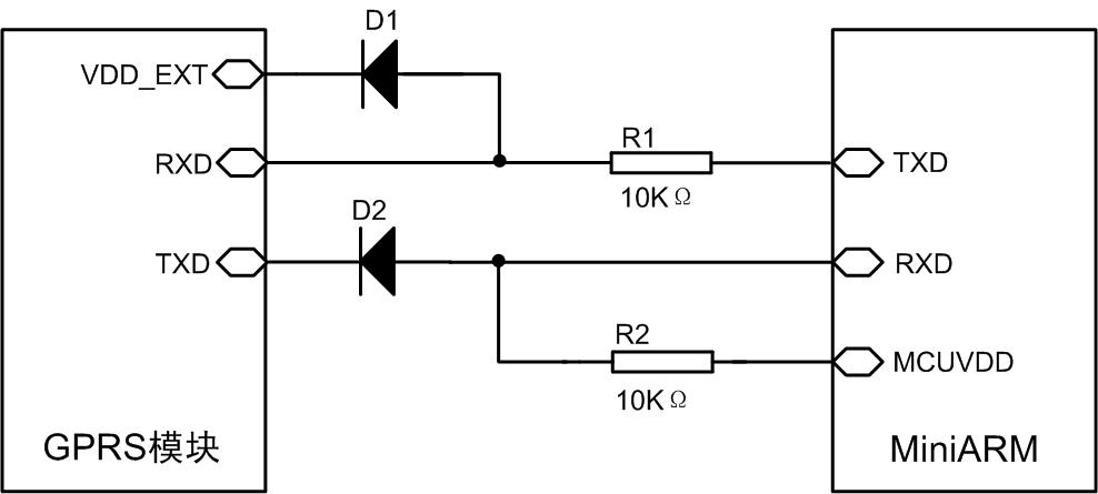
2. The diode clamping method uses diodes to achieve level matching, using the MiniARM core board and the GPRS module as examples.
When the GPRS module TXD is at a high level, due to the clamping action of the diode D2, the MiniARM RXD will get a 2.8V+VF high level voltage.
When the TXD of the MiniARM is high, due to the clamping effect of the diode D1, the RXD of the GPRS module will get a high voltage of 2.8V+VF.
Use this circuit should pay attention to:
1. The series resistance R1 of the TXD output of the MiniARM is used to limit the current, while R1 limits the communication speed between the two.
2. The TXD output of the MiniARM will input current to the VDD_EXT power supply of the GPRS module through the diode D1 to prevent VDD_EXT overvoltage.
3. GPRS module TXD VOL maximum value is 0.1V, when the output is low, due to the clamping effect of the diode, MiniARM RXD voltage is 0.1V + VF, the low voltage should be lower than VIL.
First introduce the above two kinds of level conversion circuit for everyone, the following will introduce several other methods.
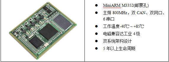
MiniARM industrial control core board has powerful functions and reliable stability. Through the selection of the series of core boards for product development, users can make the product development process shorter and the products developed more reliable. Its brief description is as follows:

For most MCUs, the pins are basically CMOS structures, so the input voltage range is: high level not lower than 0.7VCC, low level not higher than 0.3VCC.
However, before introducing the level conversion circuit, we need to first understand the following points:
1. Solve the level conversion problem, the most fundamental is to solve the level of compatibility issues, and there are two levels of compatibility principles: 1VOH> VIH2VOL
Figure 1 Threshold voltage
2. For multi-power systems, some devices do not allow the input level to exceed the supply voltage. For devices with similar requirements, the circuit should be properly protected.
3. The level shifting circuit will affect the communication speed, so you should pay attention to the communication speed requirement when using.
4. The driving ability of different conversion methods is different, and should be considered properly in the selection.
5. When there are many ways to convert, improper selection of the conversion method will result in more components or inconvenient wiring.
The following uses the example of Zhiyuan Electronics MiniARM core board to share the commonly used level conversion circuit method.
1. Resistive voltage divider The resistive voltage divider method is the simplest method. The circuit works by dividing the logic level high. Take the communication between the MiniARM core board and the GPRS module as an example. The IO level of the MiniARM core board is 3.3V, while the IO level of the GPRS module is 2.8V, and the level matching can be achieved by using FIG. 2 when communicating between the two.
Figure 2 resistance divider method
The resistive voltage conversion circuit is tested and the converted waveform is shown in Figure 3.
Figure 3 level conversion waveform
2. The diode clamping method uses diodes to achieve level matching, using the MiniARM core board and the GPRS module as examples.
Figure 4 Diode clamping method
When the GPRS module TXD is at a high level, due to the clamping action of the diode D2, the MiniARM RXD will get a 2.8V+VF high level voltage.
When the TXD of the MiniARM is high, due to the clamping effect of the diode D1, the RXD of the GPRS module will get a high voltage of 2.8V+VF.
Use this circuit should pay attention to:
1. The series resistance R1 of the TXD output of the MiniARM is used to limit the current, while R1 limits the communication speed between the two.
2. The TXD output of the MiniARM will input current to the VDD_EXT power supply of the GPRS module through the diode D1 to prevent VDD_EXT overvoltage.
3. GPRS module TXD VOL maximum value is 0.1V, when the output is low, due to the clamping effect of the diode, MiniARM RXD voltage is 0.1V + VF, the low voltage should be lower than VIL.
First introduce the above two kinds of level conversion circuit for everyone, the following will introduce several other methods.
MiniARM industrial control core board has powerful functions and reliable stability. Through the selection of the series of core boards for product development, users can make the product development process shorter and the products developed more reliable. Its brief description is as follows:
K Series Shape Molding Machine
Eps Foam Box Machine,Thermocol Box Machine,Eps Decoration Product Machine,High Configuration Eps Machine
Zhejiang Huasheng Machinery Equipment Co.,Ltd , https://www.zjhsfoammachine.com